
Floats for continuous level measurement
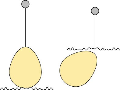
Another method of direct level measurement is the use of buoys or floats. In this case, elements with a specific mass lower than the fluid to be measured are used, so that, according to the variation in the level, the position of the float in relation to the bottom varies. This movement can be coupled to a device for visualization. Such a device can be mechanical or electronic, as shown in Figure 1.1.
 |
| Figure 1.1: Use of floats for level measurement. |
Here monitoring is continuous, as there will be an output associated with the level throughout the entire extension.
Floats for point level measurement
There are cases where only boundary points and intermediate points are sufficient. In this case, detectors popularly known as switches can be used, which can be mechanical or magnetic. Figure 1.2 shows photographs of float-type level sensors that use reed-switch switching.
 |
| Figure 1.2: Photographs of commercial level detectors with switches that use a float, an internal magnet, and a reed switch. |
In this case, the float is attached to an arm that works as a lever. As the level changes, the float containing a magnet moves towards the magnetic detector, which converts the mechanical movement into an electrical drive. The same scheme can be implemented with mechanical switches, simply using a mechanical switch activated by the movement of the arm instead of the magnet and the magnetic detector, as exemplified in Figure 1.3. This device is used in most water level controls in residential reservoirs.
 |
| Figure 1.3: Activation of a level detector by means of a mechanical arm switching a valve. |
The use of reed-switches type magnetic detectors also makes it possible to attach permanent magnets to floats that slide on an axis. As they move, these floats approach the magnetic position detectors (reed-switches) and make it possible to drive directly electrically or interface information to a microprocessor-based system that makes the decision.
The working diagram of a reed-switch together with the float and the magnet sliding over the shaft can be seen in Figure 1.4. Figure 1.5 shows a photograph of sensors of this type.
 |
| Figure 1.4: Scheme of using magnetic detectors for level monitoring. |
%20single%20point%20and%20(b)%20(near)%20continuous%20level%20detectors..png) |
| Figure 1.5: Photographs of (a) single point and (b) (near) continuous level detectors. |
It is often necessary to detect more than one or more than two level points, normally using multipoint detectors. The operation of these devices follows the same principle discussed. The only difference is that there are more floats and reed-switches in the sensor body.
The sensor in Figure 1.5(b), however, consists of a float with a magnet and a rod, in which several reed-switches are inserted that are switched according to the displacement of the float. At one end of the reed-switches there are still resistors, which are being inserted into the circuit, so that the output signal is current.
In addition to the previously described methods, there are other types of mechanical switches for level monitoring. One example is mercury detectors. In this case, we have a capsule with two mechanical contacts, partially filled with mercury (Hg). As a metal, mercury can conduct current.
The contacts are constructed in such a way that they only close when the level passes a certain threshold, when the capsule tilts. Figure 1.6 shows a sketch of this type of sensor.
 |
| Figure 1.6: Mercury capsule for level monitoring. |
Post a Comment